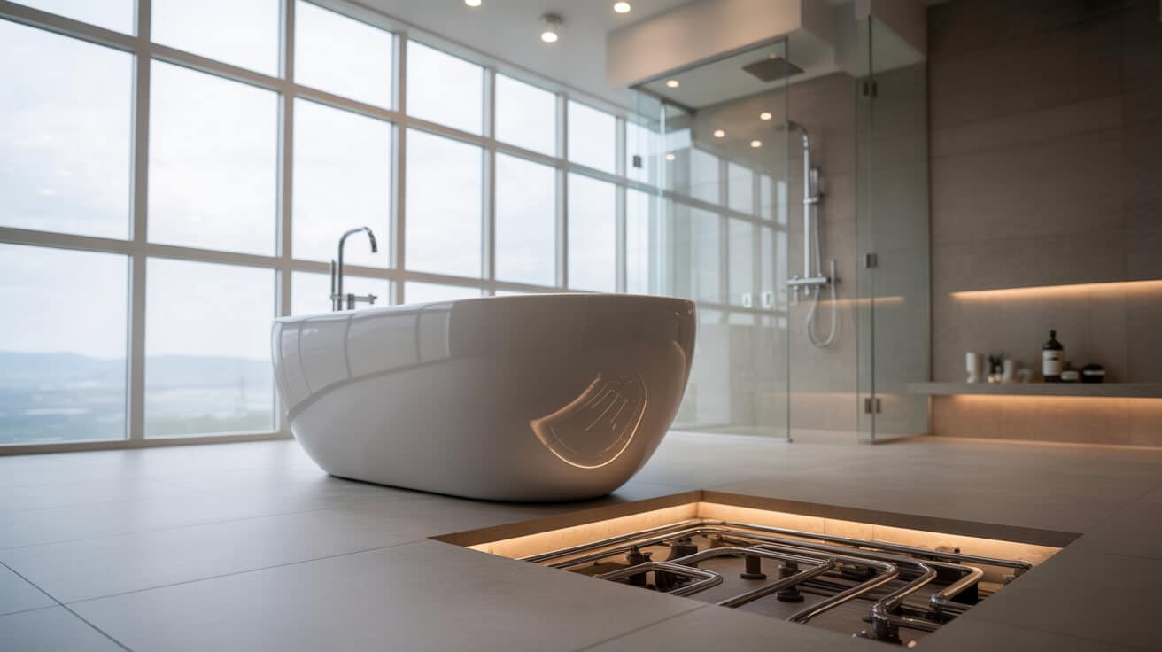
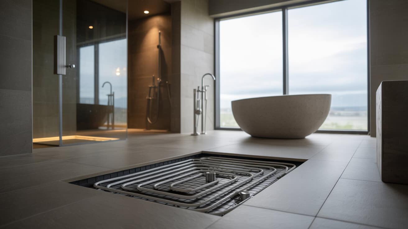
Underfloor heating utilises a distributed network of heating pipes or cables to radiate warmth uniformly from the floor. Unlike conventional radiators, which create strong vertical temperature gradients, underfloor systems promote a low, even ambient warmth beneficial to comfort, energy efficiency, and spatial aesthetics. Application spans both new construction and retrofits, with each installation method tailored to floor composition, insulation values, and heating loads. Professionals such as Plumbers 4U orchestrate system specification, installation, and commissioning using advanced calculations, materials, and zoning strategies, ensuring your requirements around comfort, usage, and efficiency are fulfilled—while remaining compliant with current regulatory and warranty frameworks.
Etymology or name origin
The term “underfloor heating” finds its roots in descriptions of heat delivered from beneath the walkable building surface. In common technical usage, abbreviations such as “UFH,” “hydronic radiant heat,” or “electric radiant floor” represent distinctions in system technology or energy transfer method. The evolution of precision terminology has coincided with the expansion of underfloor heating as a professional service, enabling clear communication among property owners, specifiers, and contractors.
Overview / context
Underfloor heating systems are distinguished by their concealed emitter design, making the floor itself a diffused heat source. Unlike point-based elements, radiant systems heat large areas at low temperatures, reducing draughts and improving comfort for occupants. Design and installation demand a holistic view, integrating architectural structure, floor build-ups, thermal performance, and user control preferences into a unified heating design. Increasingly, the integration of these systems into building automation and smart control platforms signals a shift towards personalised, responsive heating solutions.
In practical terms, underfloor systems are engineered to operate efficiently within domestic, commercial, and public sector environments. Whether seeking a minimalist aesthetic for your home or delivering adaptive zone control in your company’s office space, the underlying engineering principles shape the comfort, energy cost, and functional flexibility of the building environment. Providers such as Plumbers 4U ensure these solutions align with emerging energy standards and sustainability goals.
History
Ancient and early precedent
Ancient civilizations integrated primitive forms of underfloor heating as early as 2,000 BCE. The Roman hypocaust system distributed heated air through sub-floor and wall cavities, while the Korean ondol used heated stones beneath floor slabs for winter comfort. These innovations established the viability of radiant floor heating despite limitations in energy sources and construction materials.
Industrial and modern emergence
The development of central heating boilers and pressure-safe pipe materials in the 19th and 20th centuries made practical, reliable underfloor heating a prospect for more buildings. Scandinavian countries pioneered hydronic systems in the mid-20th century, utilising plasticized pipe and concrete screed beds. These advances paralleled the expansion of central heating infrastructure more generally, encouraging wider adoption in cold climates.
Contemporary evolution
Technological refinement since the 1980s—including the advent of cross-linked polyethylene (PEX) pipes, purpose-made insulation panels, and electronic control modules—has accelerated the inclusion of underfloor systems in both residential and commercial property design. Policy frameworks (such as UK’s Building Regulations Part L and EPC mandates) and the innovation of low-temperature boiler and heat pump solutions have further solidified underfloor heating’s place within the broader field of building services engineering.

Concept / description
Core principles of radiant floor heating
Underfloor heating functions by transferring heat from embedded elements—pipes for hydronic systems, or cables for electric systems—into the mass of the floor, from where it is radiated into occupied space. Thermal comfort is enhanced by even heat spread, limited air movement, and relatively low surface temperature throughout the floor.
Component systematics
Comprehensive system design incorporates:
- Heat generator: Boiler, heat pump, or electrical circuit providing thermal input.
- Distribution manifold: Aggregates supply/return loops, integrating flow control and balancing.
- Heat emitter array: PEX or multilayer pipes for water, electric cables or mats for resistive systems.
- Insulation and base layers: Rigid foam or XPS panels, vapour membrane, or structural substrates.
- Screed and surface: Concrete, anhydrite, or modular overlays providing thermal mass and protection.
- Controls: programmable thermostats, wired or wireless actuators, and multi-zone logic.
- Sensors: Embedded probe thermometers (floor, air), optional humidity or occupancy detectors.
Installation typologies
Designs vary depending on floor construction:
- In-screed embedding: Suitable for new-build applications, providing high thermal mass.
- Dry/overlay methods: Boards or profiled panels lay over timber floors in renovations.
- Low-profile/retrofit solutions: Allow installations for minimal elevation gain, achieving comfort in legacy buildings without major structural change.
- Modular zoning: Multiple manifolds and control points for partitioned or complex spaces.
Functionality / purpose / applications
Underfloor heating serves as core or supplementary space heating in numerous contexts. The approach permits uniform space conditioning for living rooms, bedrooms, kitchens, and bathrooms, offering floor-level warmth well-suited to high-use zones. In office complexes, retail facilities, and public spaces, underfloor systems can enable large-area heating with minimal transmitter clutter, maximising layout flexibility and reducing cleaning burdens.
Integration with building systems
- Hybridization: Combining underfloor heating on lower floors with conventional radiators or fan coils above.
- Smart building management: Integration into building automation, maximising energy-saving logic and remote control.
- Renewable energy compatibility: Effective for use with heat pumps, solar thermal arrays, and low-water-temperature systems due to large emitter area and low thermal inertia.
Classifications / types / variants
Hydronic (wet) systems
Hydronic designs circulate warm water through closed pipework loops. These are suitable for extensive installations and connect easily to boilers, solar thermal stores, or heat pumps. System configuration considers:
- Pipe material and diameter (typically 16–20 mm PEX or composite)
- Loop length and return flow balancing to achieve uniformity
- Manifold configuration with individual room zoning
- Thermal insulation depth and type to minimise downward loss
Electric (dry) systems
Electric systems fit resistive cables or flexible heating mats beneath the surface. These provide rapid response and suitability for small or isolated areas, such as bathrooms or kitchens. Characteristics include:
- Lower up-front complexity but higher operating cost per kWh (especially in non-renewably powered markets)
- ease of installation in existing rooms
- Direct integration into programmable controls for zone heating
Low-profile and retrofit variants
Advances in proprietary overlay panels, micro-pipe technology, and thin heating mats enable installations with minimal floor buildup—critical for renovations or historic properties. These allow underfloor systems’ benefits to extend into virtually any occupied space without disruptive reworking of structural floors.
Hybrid solutions and zone designs
Hybrid systems mix underfloor heating with other emitter types, maximising efficiency and comfort for your unique property layout. Flexible control placement, sensors, and logic boards enable customised heating for multi-room, open-plan, or specialty environments.
Systems / tools / methodologies
Heat load and sizing methodologies
Robust design starts with calculating heat loss through building fabric (floors, walls, glazing). Accurate calculations, often assisted by software packages, determine optimal emitter size, loop spacing, and flow temperature for your space.
Example Calculation Table
| Parameter | Typical Value | Impact on Design |
|---|---|---|
| U-value (floor) | 0.25 W/m²·K | Lower U = less heat loss, tighter loops |
| Room area | 15–100 m² | Larger areas = more circuits/zones |
| Design temp diff. | 20°C | Influences emitter temp/output |
| Pipe spacing | 100–250 mm | Tighter spacing = higher heat output |
Energy modelling and simulation
Packages model dynamic loads, system cycles, and occupancy factors, generating scenarios for various usage profiles or insulation upgrades. This supports achieving both regulatory compliance and optimal comfort.
Material selection and specification
Guided by pressures, flow rates, and heating curves, material selection weighs durability, compatibility, and cost considerations. Manifold, actuator, and mixing valve choices set the basis for control, balancing, and zone logic.
Installation methodologies
Standard procedures are followed by qualified plumbers including:
- Pre-instal survey and marking, ensuring slab compatibility.
- Sequential installation—insulation, vapour barriers, pipe or mat fixing.
- Manifold fit-out and pressure testing prior to screed or overlay.
- Integration with controls and final test protocol adherence.
- As-built documentation and client/occupant handover.

Materials and core components
Pipework
Cross-linked polyethylene (PEX), polybutylene, and multi-layered composite pipes support hydronic systems, offering corrosion resistance and flexibility. For electrics, copper or alloy-reinforced conductors, sheathed for safety, are embedded in mats or cable systems.
Insulation and membrane layers
Properly specified insulation—commonly extruded polystyrene (XPS), polyurethane foam, or phenolic boards—prevents heat loss and supports uniform surface emission.
Coverings and overlays
Cementitious screeds, dry composite boards, and proprietary overlays each supply different mass, responsiveness, and compatible flooring types. Product choices can influence both performance and build-up space required.
Manifolds, valves, and controls
Manifold assemblies contain supply/return balancing, pressure gauges, and provision for zone or room-by-room actuation. Representative installations—such as those by Plumbers 4U—employ digital thermostats, wireless sensors, and integration interfaces for centralised or decentralised control.
Sensors and feedback modules
Contemporary systems may incorporate floor and room temperature sensors, humidity probes, and occupancy or presence feedback for dynamic adjustment.
Performance metrics / data / measurements
Thermal output and coverage
System heat output varies with emitter area, pipe/mat density, and supply temperature, generally achieving 60–200 W/m². Careful balancing is required to achieve comfort and energy savings without overheating or cold spots.
Typical Output Table
| Flooring Type | Output Range (W/m²) | Warm-up Time (min) |
|---|---|---|
| Tile/stone | 120–200 | 30–60 |
| Wood/laminate | 80–140 | 45–90 |
| Carpeted | 60–100 | 60–120 |
Efficiency and energy consumption
Low-temperature operation matches current energy policy goals and heat pump compatibility. With well-insulated floors and smart controls, UFH can support EPC improvements for your property or organisation.
Measurement and commissioning
Key performance verification includes:
- Flow and return temperature measurement for each zone or loop
- Pressure tests for hydronic installations
- thermal imaging or point temperature mapping (during commissioning or diagnostics)
- Regular control/sensor calibration and functional testing
Installation processes
Survey and planning
Site-specific planning considers insulation, loading, and layout, optimising loop design for structural and aesthetic needs. As-built planning and documentation are collected for long-term service.
Substrate preparation
Insulation and vapour control layers are installed to prevent heat loss and condensation. Correct levelling and marking ensure accuracy for pipe or mat fixation.
Circuit installation
Pipe or cable is laid in conformably engineered patterns, clipped or stapled as specified. Zoning is finalised per user requirements, with manifold and circuit labelling.
Manifold and control system integration
Physically and electrically, controls interface all components: balancing valves, actuators, thermostats, and feedback devices. At the manifold, flow rates and system pressures are tested for design conformance.
Screed or overlay finishing
Based on project requirements, cement-sand, anhydrite, or dry panels encase the emitters, creating a uniform distribution surface and protecting heating elements from wear.
Final commissioning
Pressure/leak tests, purge of air, configuration of time and zone controls, and final walk-through (including documentation handover) are completed before service entry.
Maintenance and service
Preventive maintenance
Effective underfloor heating depends on routine technical checks, including:
- System flushing and inhibitor dosing every 5–10 years (hydronic)
- Bleeding air from circuits to prevent cold spots
- Calibration of sensors and controls
- Inspection of manifolds, actuators, and electrical wiring
Troubleshooting and diagnostics
Visible symptoms (cold zones, slow warm-up, controller errors) are resolved through targeted stepwise diagnosis: verifying flow, checking sensor/output values, and isolating mechanical or electronic failures. Providers such as Plumbers 4U prioritise well-documented aftercare, ensuring your system remains reliable over the long term.
Warranty and durability
Well-maintained systems with quality pipework and installation can exceed 50 years of service life, often backed by manufacturer and installer warranties when professionally commissioned.
Legal, regulatory, and industry standards
National and international codes
UK compliance pillars include:
- Building Regulations Part L: Mandates efficiency standards for heating installations.
- Part G: Addresses sanitary hot water provision.
- Part P: Requires certified safe electrical works.
- BS EN 1264: Establishes hydronic system performance criteria.
- WRAS: Approves water fittings and system materials.
- G3: Enforces unvented hot water cylinder safety.
Certification and documentation
Installers are required to be certified (Gas Safe, WRAS, MCS, CIPHE) and maintain up-to-date records for projects, handover, and maintenance. Properties meeting or exceeding these standards benefit from insurance protection and seamless future upgrades.
Challenges / barriers / limitations
Technical and architectural barriers
- Restrictive floor build-up allowances can limit emitter choices.
- Floor coverings (e.g., thick carpets) may reduce heating effectiveness.
- High initial installation costs compared to radiator-based systems.
- Retrofit projects may require staged interventions to avoid prolonged disruption.
- Return on investment improves with long-term occupancy; cost avoidance is less immediate for short tenancies.
- User education is essential for achieving operational savings and longevity.
- Misconceptions regarding maintenance or repair complexity can reduce adoption.
Behaviour and perception
- Comfort expectations and experience with conventional heating may bias initial attitudes.
- Trusted service provision and educational resources help bridge the gap.
Impact / influence / legacy
Comfort and health
Even temperature gradients, minimal air movement, and a reduction in cold surfaces deliver tangible improvements in comfort for you, your family, or organisation occupants. The removal of surface radiators improves cleaning and design flexibility.
Regulatory and industry impact
Widespread adoption impacts property compliance, energy policy achievement, and professional upskilling requirements.
Asset and value implications
Modern UFH installations can increase property marketability, value, and tenant retention while reducing operating costs for your building or business.
Service evolution
Professional providers have shifted from transactional supply to lifecycle comfort solutions, including smart controls, routine aftercare, and upgrade pathways.
Future directions, cultural relevance, and design discourse
Emerging technology and integration
AI-enhanced learning thermostats, wireless sensor networks, and low-carbon heat sources shape the next evolution in underfloor heating. Developments in phase-change materials and graphene emitters signal further improvement in performance and flexibility.
Sustainability and policy trends
Decarbonization goals and government grant frameworks (e.g., ECO, BUS) incentivize widespread UFH adoption, especially in tandem with low-temperature heat pumps and renewable power.
Evolving professional standards
Continuous development of codes and installation best practice expands long-term system reliability and your confidence as a property owner or occupier.
Changing perceptions and design values
Cultural shifts prioritise hidden, comfortable, and sustainable infrastructure—making underfloor heating an emblem of modern, adaptable, and healthy environments.

